Switching from Cast-in-Place to Precast Concrete Is Not a Materials Decision
Most teams that run into trouble on precast projects make the same mistake at the start: they treat the switch to precast as a specification change. Update the drawings, adjust the programme, and keep the same structural grid. Job done.
It isn’t job done. The two systems behave differently at a structural level. If that’s not addressed before design starts, the project pays for it later through redesign costs, programme delays, and connections that don’t perform as intended.
The Core Difference: How the Structure Carries Load
Cast-in-place reinforced concrete frames form continuous bonds at beam-column joints. The concrete sets across those joints, allowing the frame to redistribute moments, develop floor diaphragm action, and tie the structure together. The whole system acts as one piece.
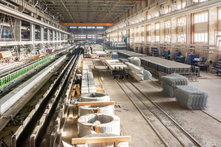
Precast frames work differently. Beams, columns, and slabs are manufactured separately and connected on site. Without deliberate continuity at those connections, the joints behave more like pins than rigid connections. Continuity can be introduced through wet joints, post-tensioning, grouted sleeve connectors, or composite toppings, but it has to be engineered in. It doesn’t arrive automatically.
That change in joint behaviour alters how forces travel through the entire structure.
What Actually Changes When You Switch
Moment distribution
Reduced continuity at connections produces little or no negative moment at supports, and much higher positive moments at midspan. EN 1992-1-1 §5.5 permits moment redistribution in continuous frames, but only where supports can rotate. Pinned precast connections cannot provide that rotation. The result is often deeper beams than the original design assumed. Alternatively, prestressing may be required to meet the deflection limits in §7.4 and the crack-control limits in §7.3.
Lateral stability
Cast-in-place frames resist lateral loads through frame action. Most precast buildings instead use shear walls, concrete cores, or braced systems. That shift changes how loads travel through columns and into foundations. Foundations sized for a cast-in-place load path may not be suitable for a precast one.
Floor diaphragm action
In cast-in-place buildings, the floor acts as a diaphragm largely because the concrete is continuous. In precast, hollowcore planks, double-tees, and solid slabs have joints that can slip under in-plane shear. EN 1992-1-1 §10.9 requires verification of shear transfer at these joints. In practice, this means structural toppings and specific joint reinforcement. Neither of these appears in a cast-in-place design.
Robustness and tying
Cast-in-place frames carry load through alternate paths when a member fails. Continuity builds that capacity in. Precast frames do not have this by default. EN 1992-1-1 §9.10 sets out specific tying rules: peripheral ties, internal ties, and vertical ties through columns and walls. EN 1991-1-7 governs the accidental design situations that drive these rules. In a precast frame, meeting them is a real design task, not something the existing reinforcement handles on its own.
The Problem That Gets Overlooked Most Often
Construction-stage load paths are entirely different from those in the finished building.
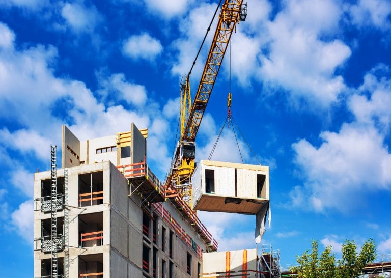
During precast erection, the structure goes through a series of temporary states: unpropped spans, incomplete floor diaphragms, and temporary bracing. EN 1991-1-6 requires that engineers treat each of these as a distinct design situation, not an afterthought to the permanent design. The erection sequence also affects how loads are distributed during construction. That means the sequence and the structural design need to be developed together.
A structure that performs well in its finished state can be unstable mid-construction. This is not an edge case. It is a routine feature of precast erection.
What Separates Projects That Work from Those That Don’t
The difference usually comes down to when the structural consequences were first addressed.
Early collaboration among the structural engineer, architect, and precast manufacturer allows the design to reflect how precast is fabricated and assembled. This needs to happen before the structural grid is fixed and the concept is locked in. It is the core principle behind Design for Manufacture and Assembly (DfMA): design the product around the process, not the other way around.
Connections as primary structural elements. In cast-in-place construction, connections between members don’t exist: the concrete is continuous. In precast, every connection has its own stiffness, capacity, ductility, and robustness. EN 1992-1-1 §10.9 requires that connections transmit the relevant actions and meet the required performance. They are not details to resolve during construction.
Construction-stage engineering at the same standard as final-state design. The erection sequence, temporary bracing, and load paths at each stage need analysis and sign-off, not assumptions.
The Cost of Getting This Wrong
Projects that apply precast to structures designed for cast-in-place tend to encounter the same problems. Connections need to be redesigned because the stiffness assumptions don’t hold. Floor build-ups occur because no one planned for a structural topping. Erection sequences need temporary works that the budget didn’t include.
Precast works well when the structure is designed as precast from the start. The problems come from treating it as something it isn’t.
Thinking About Precast for an Upcoming Project?
If you’re at early-stage development and considering precast or industrialised construction, the time to work through the structural strategy is now, before detailed design starts. The decisions made at this stage determine whether precast delivers the programme and cost efficiencies it’s capable of, or whether it creates coordination problems that take time and money to resolve.
Get in touch at leanprecast.com to discuss our approach to early-stage precast strategy.